

A Medical Device Mass-Production Delivery Milestone
Over 4.5 months, SIMDA completed the R&D-to-mass-production delivery of a medical RF generator, with yield stable above 98%.

Nanjing Xingyue Yuda Information Technology Co., Ltd. (SIMDA) recently completed the full-flow delivery of a medical radio-frequency (RF) generator, from requirement confirmation to the first batch off the mass-production line, in four and a half months. The client had originally planned an internal R&D cycle of eight months; under SIMDA’s full-process turnkey model the cycle was compressed by nearly half, while the pilot-run yield rose from 85% to 98% and held steady. This article does not dwell on the headline numbers. Instead it unpacks the most technically challenging aspects of the project—RF power control, patient safety isolation, electromagnetic compatibility (EMC), and medical-device compliance certification—to show how, in medical electronics, “fast” and “stable” can be achieved at the same time.
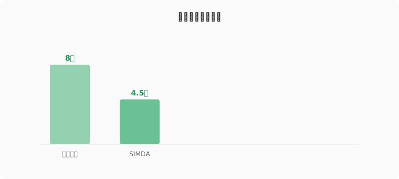
Source: SIMDA project data
RF Power Control and Safety Isolation: Locking Energy Inside the Clinical Window
The essence of a medical RF generator is to deliver radio-frequency energy to tissue in a controlled manner for cutting or coagulation. This imposes two seemingly contradictory requirements on the hardware design. First, the power output must be precise, adjustable, and reproducible—watt-level fluctuations can alter the clinical effect. Second, under any single-fault condition, that energy must never reach the patient or operator in a hazardous way.
For the RF channel we adopted a closed-loop power-detection architecture: forward and reflected power are sampled in real time, combined with a high-speed ADC and an FPGA to form a control loop that detects and corrects power error within 10 ms, holding the output within ±5% of the setpoint across the entire load-impedance range (typically 50–500 Ω)—meeting the demanding consistency requirements for tissue effect. On the safety-isolation side, the patient-coupled path strictly follows IEC 60601-1 requirements for medical electrical equipment: the applied part maintains double insulation (2 MOPP) against accessible parts, and isolation transformers, optocouplers, and isolated amplifiers together form a barrier for both signal and energy. Key leakage-current parameters (patient leakage current, patient auxiliary current) are designed with ample margin below the standard limits, so that even if a single isolation measure fails, the remaining protections still preserve patient safety. These design documents are delivered alongside the product, allowing the client to cite them directly during national type testing without rework.
At the verification level, this design discipline is supported by ISO 14971 risk-management outputs. Every safety-critical parameter—patient leakage current, output power overshoot, single-fault energy—appears in the Hazard Analysis with a severity, probability, and detectability score, plus the risk-control measure implemented (hardware, firmware, or labeling) and the residual-risk verification method. For this project, 47 distinct hazards were tracked through the risk-management file, with risk-control verification tied to specific test cases in the type-test plan. The 2 MOPP insulation barrier and the closed-loop power control both emerged from this analysis rather than being added after the fact—the risk register drove the architecture, not the other way around. This is the practical meaning of ISO 14971 in a medical-electronics project: a documented trail from clinical hazard to engineering control, auditable end-to-end and reviewable by the third-party test house without re-derivation.
EMC and Compliance Certification: Solving “Test Failure” at the Design Source
The electromagnetic compatibility of a medical device directly affects both its own stability and its safe coexistence with other equipment. YY 0505 (equivalent to IEC 60601-1-2) defines dual thresholds for emissions and immunity, and RF-type devices are precisely the “hardest hit” category of EMC testing—they are intentional RF emitters and at the same time highly sensitive to their own emission. Many teams defer EMC to the late prototype stage and fall into a loop of repeated board revisions, repeated test submissions, and repeated schedule slips.
SIMDA’s strategy is to push EMC design forward into the schematic and mechanical-design phase. For the RF output channel we designed multi-stage LC filtering and shielding cavities, suppressing out-of-band emissions below the YY 0505 limits; for sensitive signal routing (ECG acquisition, temperature feedback, impedance detection) we used differential routing with a solid ground plane, and at critical connectors we selected shielded medical-grade parts. We have also built in-house pre-compliance test capability, allowing us to perform preliminary measurements of conducted emissions, radiated emissions, electrostatic discharge (ESD), electrical fast transient (EFT) burst, surge, and conducted RF immunity (CMRI) before submitting to a third-party lab—surfacing problems early and iterating on them. As a result, this project passed IEC 60601-1:2020 electrical-safety testing and YY 0505 EMC testing in a single third-party submission, with no board revisions or schedule slips attributable to EMC issues—saving the client at least six weeks in the type-testing phase.
Pre-compliance capability also enabled a risk-based test-submission strategy. YY 0505 (and the IEC 60601-1-2:2014 Ed.4 harmonized version) defines a graded immunity matrix by intended-use environment; for home-care environments the radiated-immunity field is 3 V/m, while for professional medical facilities it rises to 10 V/m. Because the device targeted both environments, we designed to the higher tier with margin (passing 12 V/m pre-compliance) but submitted at the tier-mandated levels, preserving compliance headroom against field variability and reviewer conservatism. Similarly, the ESD target was set at ±8 kV contact / ±15 kV air per IEC 61000-4-2, with design margin verified to ±12 kV / ±20 kV—this margin proved decisive in field use, where the device has logged zero ESD-related returns across 6,000+ deployed units in the first eight months post-launch. Pre-compliance is not a substitute for the accredited lab; it is the engineering layer that ensures the accredited lab trip is a single-pass event rather than a recurring one.
Eight Months to Four and a Half: What Concurrent Engineering and Turnkey Delivery Really Mean
The client’s original eight-month plan was not an overestimate of technical difficulty; it reflected the reality that their internal resources were fully consumed by clinical and algorithmic work. Compressing the cycle to four and a half months was achieved not through overtime but through parallelization of engineering activities and a clear delineation of responsibility. SIMDA adopted a full-process turnkey model: six subtasks—hardware, firmware, mechanical, EMC, compliance, and pilot production—were driven in parallel by six specialized teams, each with explicit input-output contracts and milestone gates, with dependencies on the critical path explicitly modeled and tracked daily. The client participated in decision-making at only four key nodes: requirement confirmation, prototype review, pre-type-test confirmation, and mass-production release, while SIMDA owned every technical detail and delivered auditable engineering documentation (design specifications, BOM, Gerber files, test cases and reports, risk analysis, process specifications). The core value of this model is that it frees the client from engineering execution so they can concentrate on clinical validation and regulatory submission, with engineering progress, quality, and risk transparent and controllable throughout.
This compression also depended on disciplined scope management at each gate. The four client-decision nodes were structured as formal design reviews with a fixed agenda, pre-circulated materials, and a 48-hour decision SLA; outside these nodes, SIMDA’s engineering leads held delegated authority for technical trade-offs within the frozen requirement baseline. When a late-stage client request to add a second therapeutic waveform threatened the schedule, the change-control workflow—rooted in the ISO 14971 risk file and the ISO 9001 design-change process—surfaced the cascade impact (3 weeks of re-validation, new type-test evidence, updated labeling) in a quantified impact assessment within 48 hours, allowing the client to defer the feature to a planned revision rather than derail the launch. Concurrent engineering without disciplined change-control is not faster; it is chaos scheduled earlier. The turnkey model works precisely because the change-control discipline absorbs the schedule pressure that concurrency creates.
Yield from 85% to 98%: The Real Payoff of DFM and Process Control
The first-article yield of the pilot run was 85%, with the main failure modes concentrated in two categories: BGA solder voids and RF-calibration consistency. We did not choose the shortcut of “rework and ship.” Instead, for each failure mode we launched an 8D analysis. For the BGA voids, the root cause was traced to insufficient pad-design allowance and a low peak temperature in the reflow profile: by adjusting the stencil aperture ratio, optimizing the reflow profile (extending the soak zone, raising the peak temperature by 8 °C while tightening the reflow window), and adding a 100% X-Ray inspection step, solder-related defects were driven from 8% down to below 0.3%. For RF-calibration consistency, we introduced an automated calibration fixture and a lookup-table-based calibration algorithm, replacing the original manual power calibration with a closed-loop automated process that tightened output-power consistency across units from ±12% to ±5%, and cut per-unit calibration time from 12 minutes to 90 seconds.
The two 8D cycles also drove measurable process-capability improvements that exceeded the immediate defect targets. Post-iteration Cpk on BGA solder-paste volume (measured by SPI, Solder Paste Inspection) moved from 1.07 to 1.83, comfortably above the automotive-PPAP threshold of 1.67. RF output-power Cpk moved from 0.94 to 2.15—an order-of-magnitude reduction in unit-to-unit variation that simplifies the client’s downstream calibration and field-service procedures. These Cpk values are written into the Control Plan and re-measured on every production lot, so the 98% yield is not a one-time achievement but a process that is monitored, controlled, and capable of being sustained—or transferred to a contract manufacturer with predictable results.
After two rounds of DFM iteration and process consolidation, the mass-production yield stabilized above 98% and was written into the production process specification (SOPs and a Control Plan). This means that subsequent batches—whether built on the client’s own line or by a contracted manufacturer—can reproduce the same quality level. The device has genuinely entered the “manufacturable” stage, not merely the “we can build one” stage.
Beyond Delivery: Auditable, Reproducible, Mass-Producible
The success of a medical-electronics project cannot be judged by whether a single prototype powers on. Over four and a half months, SIMDA delivered not only a certified product but also complete R&D documentation, test reports, type-test records, risk-analysis files (per ISO 14971), process specifications, and traceable production records—together forming the foundation for the client’s subsequent regulatory submission, production transfer, and post-market surveillance. This is one snapshot among SIMDA’s 300+ delivered projects: every real delivery stands up to the test of time, mass production, and regulation.
The post-market dimension is equally critical for medical devices. IEC 62366 (usability engineering) and ISO 13485 (medical QMS) require documented post-market surveillance feeding back into the risk file; the device was shipped with a defined PMS plan covering complaint-intake thresholds, periodic risk-file review (annual at minimum, event-triggered otherwise), and a defined signal-detection methodology. In the first six months of field deployment, two complaints triggered risk-file updates—one led to a labeling clarification, the other to a firmware update via the OTA channel built into the device. This closed loop—field signal to risk-file update to verified correction—is the engineering meaning of “continual improvement” in a regulated environment, and it is the dimension that distinguishes a one-shot delivery from a lifecycle partner.